- ←Prev
- AST
A Library for Handling
World Coordinate Systems
in Astronomy - Next→
- TOC ↑
9 Spectral Coordinate Systems (SpecFrames)
The ?? is a ?? which is specialised for representing coordinate systems which describe a position
within an electro-magnetic spectrum. In this section we examine the additional properties and
behaviour of a SpecFrame that distinguish it from a basic Frame (§7).
9.1 The SpecFrame Model
As for a ??, a ?? is a ?? (§7) and also a ?? (§5), so it inherits all the properties and behaviour of
these two ancestral classes. When used as a Mapping, a SpecFrame implements a unit
transformation, exactly like a basic Frame (§7.3) or a ??, so this aspect of its behaviour is not of great
importance.
When used as a Frame, however, a SpecFrame represents a wide range of different 1-dimensional
coordinate system which can be used to describe positions within a spectrum. The options available
largely mirror those described in the FITS-WCS paper III Representations of spectral coordinates in FITS
(Greisen, Valdes, Calabretta & Allen).
9.2 Creating a SpecFrame
The ?? constructor function is particularly simple and a SpecFrame with default attributes is created as
follows:
INCLUDE ’AST_PAR’
INTEGER SPECFRAME, STATUS
STATUS = 0
...
SPECFRAME = AST_SPECFRAME( ’ ’, STATUS )
Such a SpecFrame would represent the default coordinate system which is heliocentric wavelength in
metres (i.e. wavelength corrected to take into account the Doppler shift caused by the velocity of the
observer around the sun).
9.3 Specifying a Particular Spectral Coordinate System
Selection of a particular coordinate system is performed simply by setting a value for the ??’s
(character string) ?? attribute. This setting is most conveniently done when the SpecFrame is created.
For example, a SpecFrame representing Energy would be created by:
SPECFRAME = AST_SPECFRAME( ’System=Energy’, STATUS )
Note that specifying “SystemEnergy”
also changes the associated Unit (from metres to Joules). This is because the default value of the
SpecFrame’s Unit attribute depends on the System attribute setting.
You may change the System value at any time, although this is not usually needed. The
values supported are set out in the attribute’s description in Appendix C and include a
variety of velocity systems, together with frequency, wavelength, energy, wave-number,
etc.
9.4 Attributes which Qualify Spectral Coordinate Systems
Many spectral coordinate systems have some additional free parameters which serve to identify a
particular coordinate system from amongst a broader class of related coordinate systems. For
example, the velocity systems are all parameterised by a rest frequency—the frequency which defines
zero velocity, and all coordinate systems are qualified by a ‘standard of rest” which indicates the rest
frame to which the values refer.
In AST, these free parameters are represented by additional ?? attributes, each of which has a default
appropriate to (i.e. defined by) the setting of the main ?? attribute. Each of these qualifying attributes
may, however, be assigned an explicit value so as to select a particular coordinate system. Note, it is
usually best to assign explicit values whenever possible rather than relying on defaults.
Attribute should only be left at their default value if you “don’t care” what value is used. In
certain circumstances (particularly, when aligning two Frames), a default value for an
attribute may be replaced by the value from another similar ??. Such value replacement can be
prevented by assigning an explicit value to the attribute, rather than simply relying on the
default.
The main SpecFrame attributes which qualify the System attribute are:
-
??
This attribute is inherited from the Frame class. It gives the moment in time
when the coordinates are correct for the astronomical source under study
(usually the date of observation). It is needed in order to calculate the Doppler
shift produced by the velocity of the observer relative to the centre of the earth,
and of the earth relative to the sun.
-
??
This specifies the rest frame in which the coordinates are correct. Transforming
between different standards of rest involves taking account of the Doppler shift
introduced by the relative motion of the two standards of rest.
-
??
Specifies the frequency which correspond to zero velocity. When setting a
value for this attribute, the value may be supplied as a wavelength (including
an indication of the units being used, “nm” “Angstrom”, etc.), which will be
automatically be converted to a frequency.
-
??
Specifies the RA (FK5 J2000) of the source. This is used when converting
between standards of rest. It specifies the direction along which the component
of the relative velocity of the two standards of rest is taken.
-
??
Specifies the Dec (FK5 J2000) of the source. Used in conjunction with REFRA.
-
??
This defines the “source” standard of rest. This is a rest frame which is moving
towards the position given by RefRA and RefDec, at a velocity given by
SourceVel. The velocity is stored internally as a heliocentric velocity, but can
be given in any of the other supported standards of rest.
For further details of these attributes you should consult their descriptions in Appendix C and for
details of the System settings for which they are relevant, see the description of the System attribute
(also in Appendix C).
Note that it does no harm to assign values to qualifying attributes which are not relevant to the main
System value. Any such values are stored, but are not used unless the System value is later set so that
they become relevant.
9.5 Using Default SpecFrame Attributes
The default values supplied for many ?? attributes will depend on the value of the SpecFrame’s ??
attribute. In practice, this means that there is usually little need to specify many of these attributes
explicitly unless you have some special requirement. This can be illustrated by using ?? to examine a
SpecFrame, as follows:
CALL AST_SHOW( AST_SPECFRAME( ’System=Vopt, RestFreq=250 GHz’, STATUS ),
: STATUS )
The output from this might look like the following:
Begin SpecFrame # Description of spectral coordinate system
# Title = "Optical velocity, rest frequency = 250 GHz" # Title
of coordinate system
Naxes = 1 # Number of coordinate axes
# Domain = "SPECTRUM" # Coordinate system domain
# Epoch = 2000 # Julian epoch of observation
# Lbl1 = "Optical velocity" # Label for axis 1
System = "VOPT" # Coordinate system type
# Uni1 = "km/s" # Units for axis 1
Ax1 = # Axis number 1
Begin Axis # Coordinate axis
End Axis
IsA Frame # Coordinate system description
# SoR = "Heliocentric" # Standard of rest
RstFrq = 250000000000 # Rest frequency (Hz)
End SpecFrame
Note that the defaults (indicated by the “#” comment character at the start of the line) for attributes
such as the ??, axis Labels and Unit specifiers are all set to values appropriate for the particular
velocity system that the SpecFrame represents.
These choices would be appropriate for a System value of “Vopt”, but if a different System value were set,
the defaults would be correspondingly different. For example, by default frequency is measured in units of
GHz, not ,
so setting “System=freq” would change the appropriate line above from:
# Uni1 = "km/s" # Units for axis 1
to
# Uni1 = "GHz" # Units for axis 1
Of course, if you do not like any of these defaults, you may always over-ride them by setting
explicit attribute values yourself. For instance, you may choose to have your frequency
axis expressed in “kHz” rather than “GHz”. To do this simply set the attribute value as
follows:
CALL AST_SETC( SPECFRAME, ’Unit’, ’kHz’, STATUS )
No error will be reported if you accidentally set an inappropriate Unit value (say "J" - Joules)—after
all, AST cannot tell what you are about to do, and you may be about to change the System value to
“Energy”. However, an error will be reported if you attempt to find a conversion between two
SpecFrames (for instance using ?? ) if either SpecFrame has a Unit value which is inappropriate for its
System value.
SpecFrame attributes, like all other attributes, all have default value. However, be aware that for some
attributes these default values can never be more than “a legal numerical value” and have no
astronomical significance. For instance, the ?? and ?? attributes (which give the source
position) both have a default value of zero. So unless your source happens to be at that
point (highly unlikely!) you will need to set new values. Likewise, the ?? (rest frequency)
attribute has an arbitrary default value of 1.0E5 GHz. Some operations are not affected by
inappropriate values for these attributes (for instance, converting from frequency to wavelength,
changing axis units, etc), but some are. For instance, converting from frequency to velocity
requires a correct rest frequency, moving between different standards of rest requires a
correct source position. The moral is, always set explicit values for as many attributes as
possible.
9.6 Creating Spectral Cubes
You can use a ?? to describe the spectral axis in a data cube containing two spatial axes and a spectral
axis. To do this you would create an appropriate SpecFrame, together with a 2-dimensional ?? (often a
??) to describe the spatial axes. You would then combine these two Frames together into a single
??.
INTEGER SKYFRAME
INTEGER SPECFRAME
INTEGER CMPFRAME
...
SKYFRAME = AST_SKYFRAME( ’Epoch=J2002’, STATUS )
SPECFRAME = AST_SPECFRAME( ’System=Freq,StdOfRest=LSRK’,
: STATUS )
CMPFRAME = AST_CMPFRAME( SKYFRAME, SPECFRAME, ’ ’, STATUS )
In the resulting CmpFrame, axis 1 will be RA, axis 2 will be Dec and axis 3 will be Frequency. If this is
not the order you want, you can permute the axes using ??.
There is one potential problem with this approach if you are interested in unusually high
accuracy. Conversion between different standards of rest involves taking account of the
Doppler shift caused by the relative motion of the two standards of rest. At some point this
involves finding the component of the relative velocity in the direction of interest. For a
SpecFrame, this direction is always given by the ?? and ?? attributes, even if the SpecFrame is
embedded within a CmpFrame as above. It would be more appropriate if this “direction of
interest” was specified by the values passed into the CmpFrame on the RA and DEC axes,
allowing each pixel within a data cube to have a slightly different correction for Doppler
shift.
Unfortunately, the SpecFrame class cannot do this (since it is purely a 1-dimensional Frame), and so
some small degree of error will be introduced when converting between standards of rest, the size of
the error varying from pixel to pixel. It is hoped that at some point in the future a sub-class of
CmpFrame (a SpecCubeFrame) will be added to AST which allows for this spatial variation in
Doppler shift.
The maximum velocity error introduced by this problem is of the order of
, where
is the angular
field of view, and
is the relative velocity of the two standards of rest. As an example, when correcting from the observers
rest frame (i.e. the topocentric rest frame) to the kinematic local standard of rest the maximum value of
is about 20
, so for
5 arc-minute field of view the maximum velocity error introduced by the correction will be about 0.03
. As
another example, the maximum error when correcting from the observers rest frame to the local group is
about 5
over a 1 degree field of view.
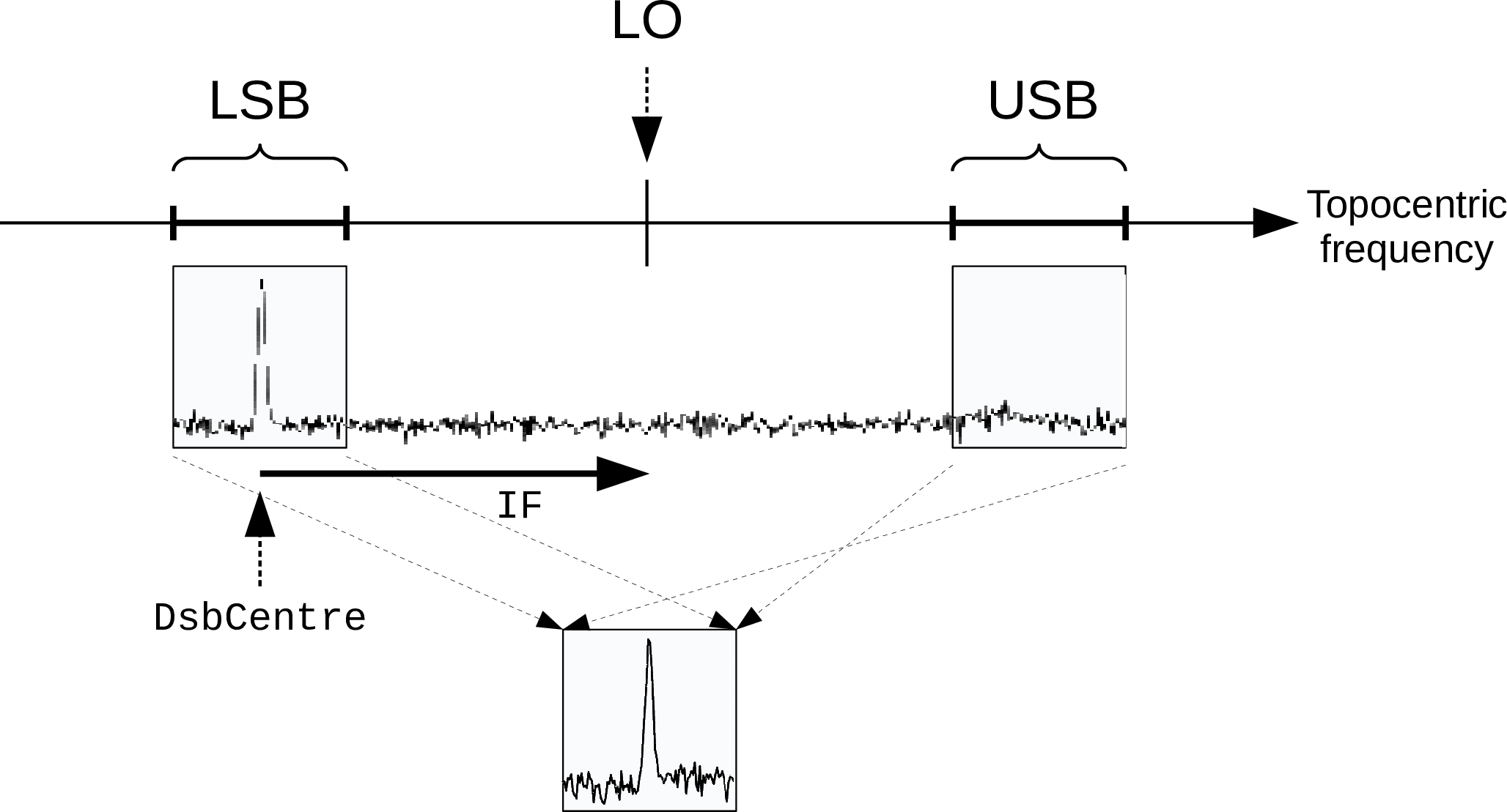
9.7 Handling Dual-Sideband Spectra
Dual sideband super-heterodyne receivers produce spectra in which each channel contains
contributions from two different frequencies, referred to as the “upper sideband” (USB) frequency and
the “lower sideband” (LSB) frequency. In the rest frame of the observer (topocentric), these are related
to each other as follows:
where
is a fixed frequency known as the “local oscillator frequency”. In other words, the local oscillator
frequency is always mid-way between any pair of corresponding upper and lower sideband
frequencies.
This is illustrated in Figure 11. The astronomical signal received in the two spectral windows (one
corresponding to each sideband) are superimposed in the final measured spectrum, with the signal
from the USB window first being reversed in frequency.
To describe the spectral axis of the final measured spectrum using a ?? you must
choose whether you want the SpecFrame to describe the frequency of the LSB window
() or of the USB
window () -
a basic SpecFrame cannot describe both sidebands simultaneously. However, there is a sub-class of
SpecFrame, called ??, which overcomes this difficulty.
A DSBSpecFrame has a ?? attribute which indicates if the DSBSpecFrame is currently being used to
describe the upper or lower sideband spectral axis. The value of this attribute can be changed at any
time. A DSBSpecFrame knows how to transform frequencies between the two sidebands. For instance,
if you have two DSBSpecFrame objects that describe topocentric frequency and are identical except
that they describe opposite sidebands, then the ?? function will return a ?? that implement equation
1. If
the DSBSpecFrames describe anything other than topocentric frequency, then the returned
Mapping will be more complicated since it will include conversions to and from topocentric
frequency.
In practice, the local oscillator frequency for a dual sideband instrument may not be easily available to
an observer. Instead, it is common practice to specify the spectral position of some central feature
in the observation (commonly the centre of the instrument passband), together with an
“intermediate frequency”. Together, these two values allow the local oscillator frequency
to be determined. The intermediate frequency is the difference between the topocentric
frequency at the central spectral position and the topocentric frequency of the local oscillator.
So:
The DSBSpecFrame class uses the ?? attribute to specify the central spectral position
(), and the ?? attribute to specify
the intermediate frequency ().
This is illustrated in Figure 11, where the values of the DSBCentre and IF attributes have been chosen
to put an emission line at the centre of the LSB window. The DSBSpecFrame determines LO from these
two attribute values.
Note, in principle there is no reason why the attribute values should not have been chosen to put the
spectral line in the USB instead of the LSB. The choice of which sideband to use for the observed
feature is usually made in order to exclude any bright features from the other window. The sideband
that contains the observation centre is known as the “observed” sideband, and the other sideband is
known as the “image” sideband.
The DSBCentre value is given and returned in the spectral system described by the DSBSpecFrame
(thus you do not need to calculate the corresponding topocentric frequency yourself - this will be done
automatically by the DSBSpecFrame when you assign a new value to the DSBCentre attribute). The
value assigned to the IF attribute should always be a topocentric frequency in units of Hz. It’s
sign indicates whether the observation centre (given by DSBCentre) is in the LSB or the
USB—a positive IF puts the observation centre in the LSB and a negative IF puts it in the
USB.
9.7.1 Aligning Dual-Sideband Spectra
Usually, a ?? will be used to describe the WCS for a 1-dimensional array of data values measured
using a dual-sideband instrument. The ?? for this sort of situation will typically contain two Frames:
the base ?? will be a simple 1-dimensional Frame describing the value used to index the data array
(i.e. “pixel” coordinates) and the current Frame will be a DSBSpecFrame with values for
the ?? and ?? attributes that match the settings of the dual side-band instrument. The ??
connecting the base (pixel) Frame to the current (spectral) Frame will depend on exactly how the
instrument samples the spectrum (linear, logarithmic, etc) but should always generate spectral
values
within the window corresponding to the value of the ?? attribute in the DSBSpecFrame. For instance, if the
SideBand attribute is set to USB, then the Mapping should generate the USB frequency (or wavelength,
velocity, etc)
for each pixel.
As an example, the following code creates a FrameSet that associates a radio velocity (km/s) in the
LSRK standard of rest with each element in an array of 1000 data values. The velocity range -100 to
100 km/s in the LSB window (see Figure 11) is mapped linearly onto the pixel array. The spectral
feature of interest is at 10 km/s (i.e. within the velocity range of the LSB window) and the IF is +5 GHz
(topocentric).
* Declare required functions and constants
INCLUDE ’AST_PAR’
INCLUDE ’SAE_PAR’
* Declare local variables.
INTEGER FRAMESET
INTEGER PIXEL_FRAME
INTEGER SPECTRAL_FRAME
INTEGER PIX_TO_SPEC
INTEGER STATUS
DOUBLE PRECISION XIN( 2 )
DOUBLE PRECISION VOUT( 2 )
* Initialise the inherited status value
STATUS = SAI__OK
* Create a Frame to describe 1-D pixel coordinates within the data
* array.
PIXEL_FRAME = AST_FRAME( 1, ’Domain=PIXEL’, STATUS )
* Create a DSBSpecFrame to describe radio velocity in the LSB window of
* the dual-sideband spectral axis.
SPECTRAL_FRAME = AST_DSBSPECFRAME( ’System=VRAD,’ //
: ’StdOfRest=LSRK,’ //
: ’Unit=km/s,’ //
: ’RefRA=7:10:04.5,’ //
: ’RefDec=-10:48:50,’ //
: ’Epoch=2020-Oct-2T12:13:56.985,’ //
: ’RestFreq=345.7959899 GHz,’ //
: ’SideBand=LSB,’ //
: ’DSBCentre=10.0,’ //
: ’IF=5.0 GHz’, STATUS )
* Create a linear mapping to describe the transformation from pixel
* coordinate to the spectral coordinate system described by spectral_frame.
* The definition of pixel coordinates used here puts the centre of the
* first pixel at pixel coordinate 1.0, corresponding to a velocity of
* -100.0 km/s, and puts the centre of the last pixel at pixel coordinate
* 1000.0, corresponding to a velocity of +100.0 km/s.
PIX_TO_SPEC = AST_WINMAP( 1, 1.0D0, 1000.0D0, -100.0D0, 100.0D0,
: ’ ’, STATUS )
* Construct the FrameSet. First create a FrameSet holding just the pixel
* Frame (which becomes the base Frame). Then add in the spectral Frame,
* using the above mapping to connect it to the pixel Frame (i.e. the base
* Frame). The spectral Frame becomes the current Frame (the base Frame
* remains the pixel Frame).
FRAMESET = AST_FRAMESET( PIXEL_FRAME, ’ ’, STATUS )
CALL AST_ADDFRAME( FRAMESET, AST__BASE, PIX_TO_SPEC,
: SPECTRAL_FRAME, STATUS )
* Use the FrameSet as a Mapping to get the range of radio velocity
* spanned by the pixel array. This is done by transforming the first and
* last pixel coordinate into radio velocity. The displayed velocity range
* should be vel_lo to vel_hi.
XIN( 1 ) = 1.0
XIN( 2 ) = 1000.0
CALL AST_TRAN1( FRAMESET, 2, XIN, .TRUE., VOUT, STATUS )
WRITE(*,*) ’The LSB window covers the radio velocity range ’,
: VOUT( 1 ),’ to ’,VOUT(2),’ km/s’
* Now change the FrameSet so that the DSBSpecFrame represents the USB
* instead of the LSB. Doing this modifies the Mapping inside the
* FrameSet so that transforming a given pixel position generates the
* equivalent USB velocity rather tha the original LSB velocity.
CALL AST_SET( FRAMESET, ’Sideband=USB’, STATUS )
* Display the range of USB radio velocity now spanned by the pixel
* array.
CALL AST_TRAN1( FRAMESET, 2, XIN, .TRUE., VOUT, STATUS )
WRITE(*,*) ’The USB window covers the radio velocity range ’,
: VOUT( 1 ),’ to ’,VOUT(2),’ km/s’
The code above should generate the following screen output:
The LSB window covers the radio velocity range -100 to 100 km/s
The USB window covers the radio velocity range -8549.46 to -8749.46 km/s
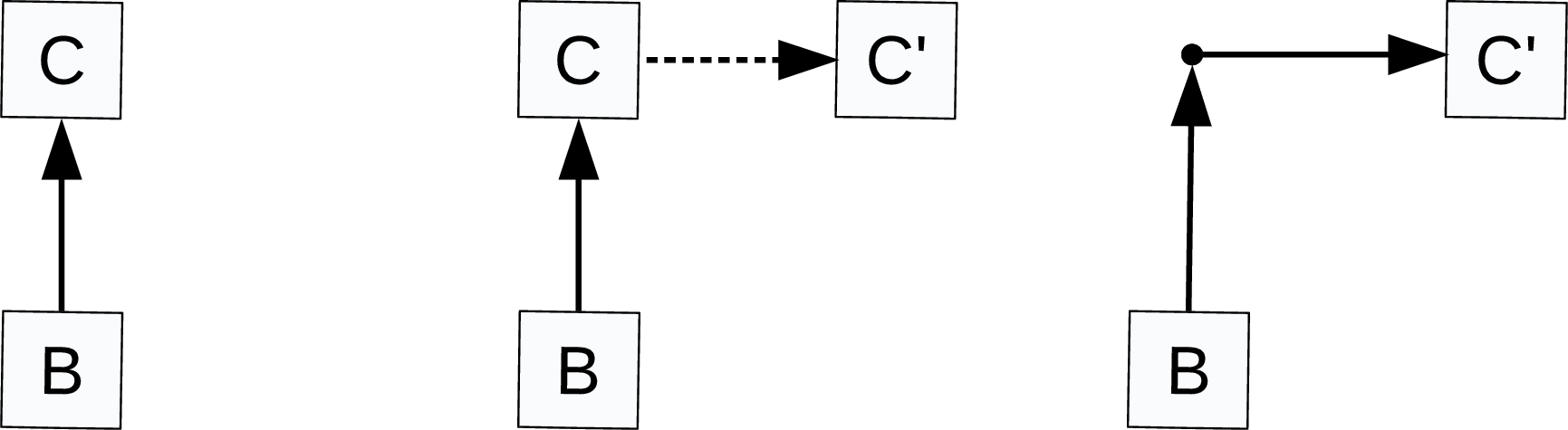
Note, changing the value of the Sideband attribute using the FrameSet pointer, as is done
above, automatically causes the Mapping inside the FrameSet to be updated to include
the mapping from LSB frequency to USB frequency. This automatic modification of the
Mappings inside a FrameSet is described further in §14.6 and illustrated in Figure 12. It relies
on the ?? function to find the Mapping that converts values from one DSBSpecFrame to
another.
When the AST_CONVERT function to used to find the Mapping between two DSBSpecFrames, it is
sometimes appropriate for it to take account of the potentially different settings of the Sideband
attribute in the two DSBSpecFrames. The above example, in which AST_CONVERT is used to modify
the Mapping inside a FrameSet to accomodate a change to the Sideband attribute of the current
Frame, is such a case - AST_CONVERT returns a Mapping that implements equation 1 in some
form.
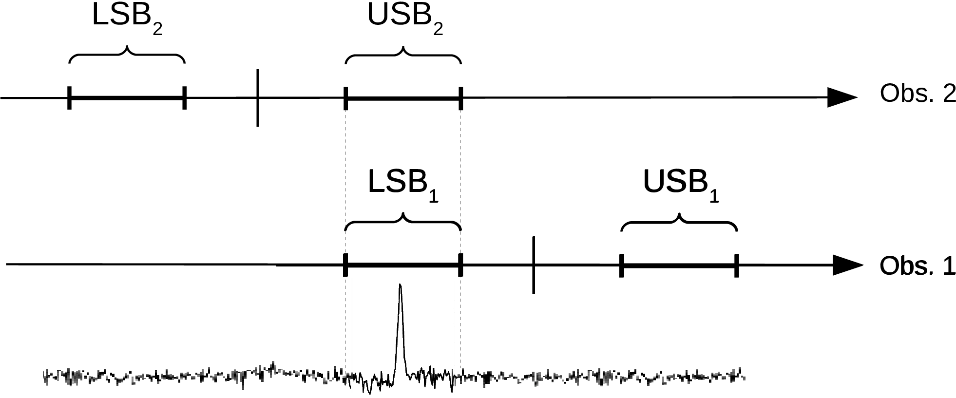
However, there are also cases where it is better for AST_CONVERT not to take account of
differences in the settings of the Sideband attribute. For instance, if a spectral line is observed
twice such that the line is in the LSB in one observation and in the USB in the other, as
illustrated in Figure 13, then it would be inappropriate to take account of this difference when
co-adding the two observations. In this case, a frequency in one observation should be
matched to exactly the same frequency in the other observation, regardless of the difference in
Sideband.
The AlignSideband attribute is used to determine whether any difference is Sideband setting should
be taken into account when finding the Mapping between two DSBSpecFrame objects. The default for
this attribute is zero, meaning that the Sideband settings are usually ignored by the AST_CONVERT
and ?? functions (i.e. the DSBSpecFrames are aligned as if they were simple SpecFrames). The one
exception is that differences in Sideband are always taken into account, regardless of the value of the
AlignSideband atribute, when using AST_CONVERT to find the Mapping required to restore a
FrameSet’s integrity following a change to the Sideband attribute in the current Frame (as described
earlier in this section).
If an attempt is made to find the Mapping between a pair of DSBSpecFrame, then the Sideband
attribute will be ignored if the AlignSideband attribute is zero in either of the DSBSpecFrames. In
other words, the Mapping will be determined as if both objects were simple SpecFrames rather than
DSBSpecFrames. This also happens if an attempt is made to align a DSBSpecFrame with a simple
SpecFrame. See §12.6 for more about how simple SpecFrames align.
If both DSBSpecFrames have non-zero AlignSideband attributes, the Mapping from one to the other is
made of three parts in series:
-
(1)
- A Mapping which converts the first DSBSpecFrame into its observed sideband
representation (i.e. the sideband that contains the DSBCentre value). If the DSBSpecFrame
already represents its observed sideband, this Mapping will be a ??.
-
(2)
- A Mapping which converts from the first to the second DSBSpecFrame, treating them as if
they were both basic SpecFrames. This takes account of any difference in units, standard
of rest, system, etc between the two DSBSpecFrames.
-
(3)
- A Mapping which converts the second DSBSpecFrame from its observed sideband
representation to its current sideband. If the DSBSpecFrame currently represents its
observed sideband, this Mapping will be a UnitMap.
Copyright (C) 2024 East Asian Observatory
- ←Prev
- AST
A Library for Handling
World Coordinate
Systems
in Astronomy - Next→
- TOC ↑