REBIN method. Note the deep
wells around bright sources and the numerous spikes caused by (simulated) cosmic rays.The processing of SCAN data with the rebin method proceeds in a multi-step approach that follows the method listed above for DREAM and STARE data using makemap. A one-pass rebinning algorithm is applied to the data, which regrids the signal from each bolometer on to a map in the desired co-ordinate system.
As outlined in F, the procedure for processing SCUBA-2 data follows these steps:
The rebinning algorithm shares the observed signal from a single bolometer between neighbouring output map pixels, as determined by the pixel-spreading function. The value of each pixel in the map is the sum of the signal from every bolometer that observed at that position.
There are many options for the pixel spreading scheme (see the wcsmosaic documentation for a summary). The fastest option is to use the nearest-neighbour pixel spreading scheme (‘Nearest’), which assigns the whole signal from one bolometer to the nearest map pixel. This option does not always produce smooth maps (if the map is poorly sampled, for example, but it produces a robust estimate of the noise. In the limit of a large number of ‘hits’ per pixel, and with a pixel size sufficiently small compared to the beamsize, this method is optimal.
For smoother maps (with poor sampling, for example), the ‘Linear’ scheme can be used to share the input signal equally among the four nearest map pixels. There are more complicated options available, e.g., Sinc-type functions, or Gaussian distributions. These methods produce aesthetically pleasing maps, at the risk of introducing correlations into the noise and additional smoothing to the map.
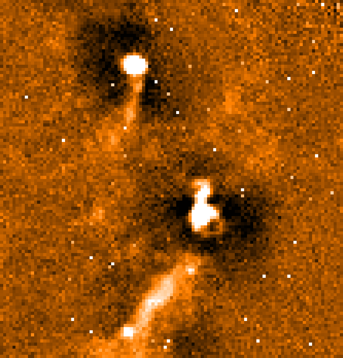
Figure 6 shows an example map created from simulated observations of an extended source with bright features. It was created using the rebin method and the nearest-neighbour pixel spreading scheme.
Note the dark regions around the bright sources. They are negative bowls introduced by the sky subtraction method (Section F.0.3). The random dots are cosmic ray spikes which are not removed by this particular workflow.

REBIN method. Note the deep
wells around bright sources and the numerous spikes caused by (simulated) cosmic rays.