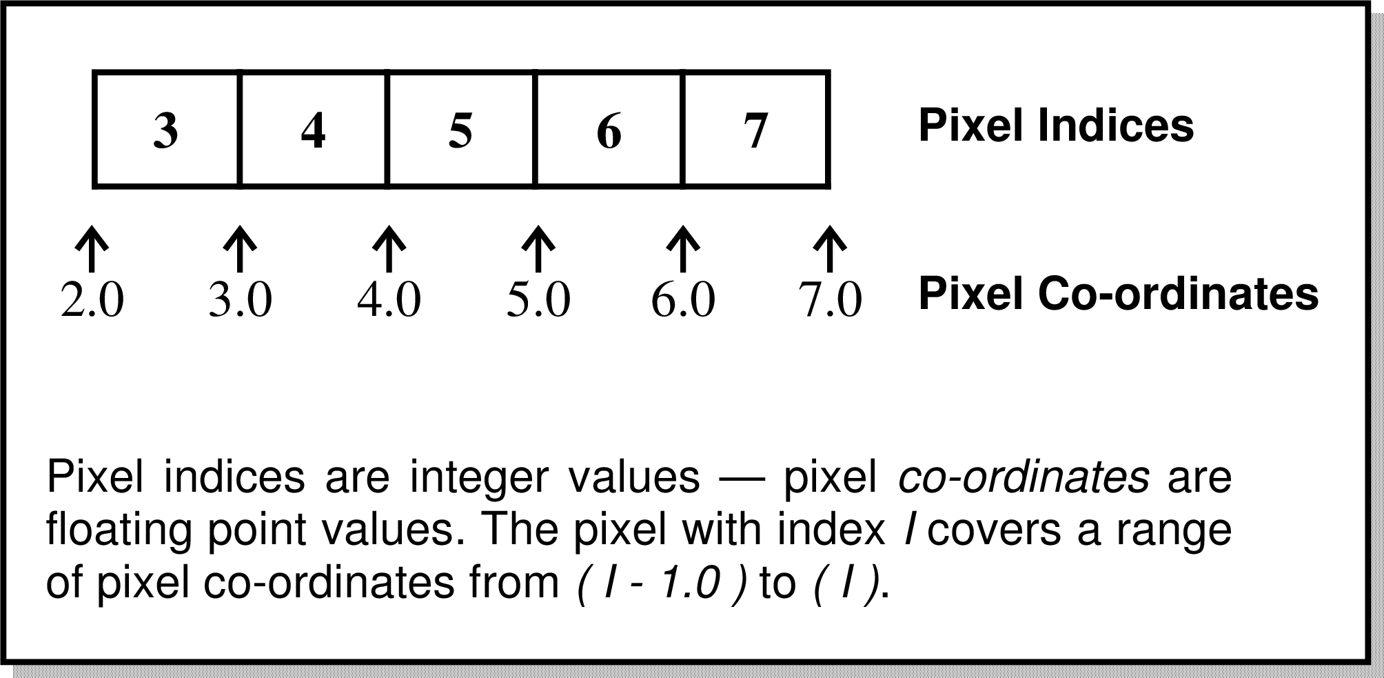
Figure 10: Pixel indices.
In this sub-section we will look at the definition of the four basic co-ordinate systems available in all NDFs—pixel indices, pixel co-ordinates, grid co-ordinates, and normalised co-ordinates.
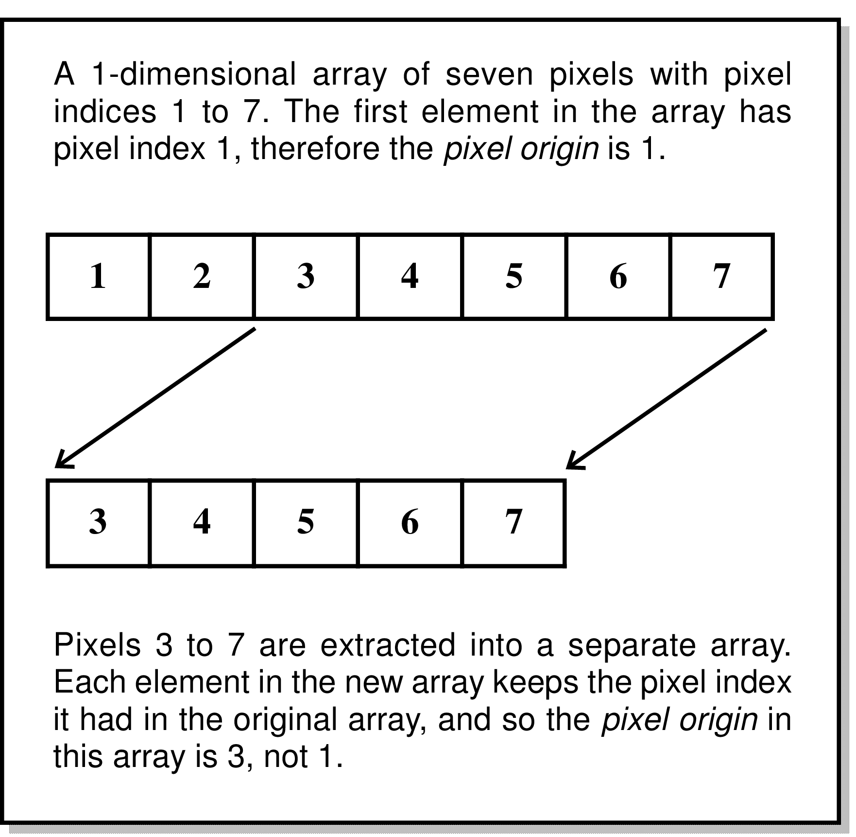
Pixel indices are integer values that are used to count the pixels along each axis of an NDF. The first pixel can be given any arbitrary pixel index, and this value is known as the pixel origin. When a section is extracted from an NDF, the pixel origin in the extracted section is set so that each pixel retains its original pixel indices (see Figure 10).
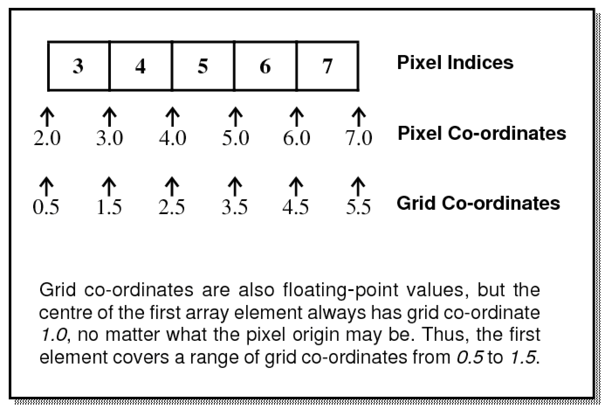
Pixel co-ordinates are floating-point values that allow positions to be specified with sub-pixel accuracy. They are related to pixel indices as indicated in Figure 11).
Grid co-ordinates are floating-point values that are similar to pixel co-ordinates except that the origin is fixed so that the first pixel on an axis is centred at a grid co-ordinate value of 1.0, no matter what the pixel origin is. This corresponds to the FITS idea of ‘pixel co-ordinates’ (FITS makes no provision for an arbitrary pixel origin). When a section is extracted from an array, the grid co-ordinates of the extracted section include no knowledge of where the section was located in the original array. See Figure 12).
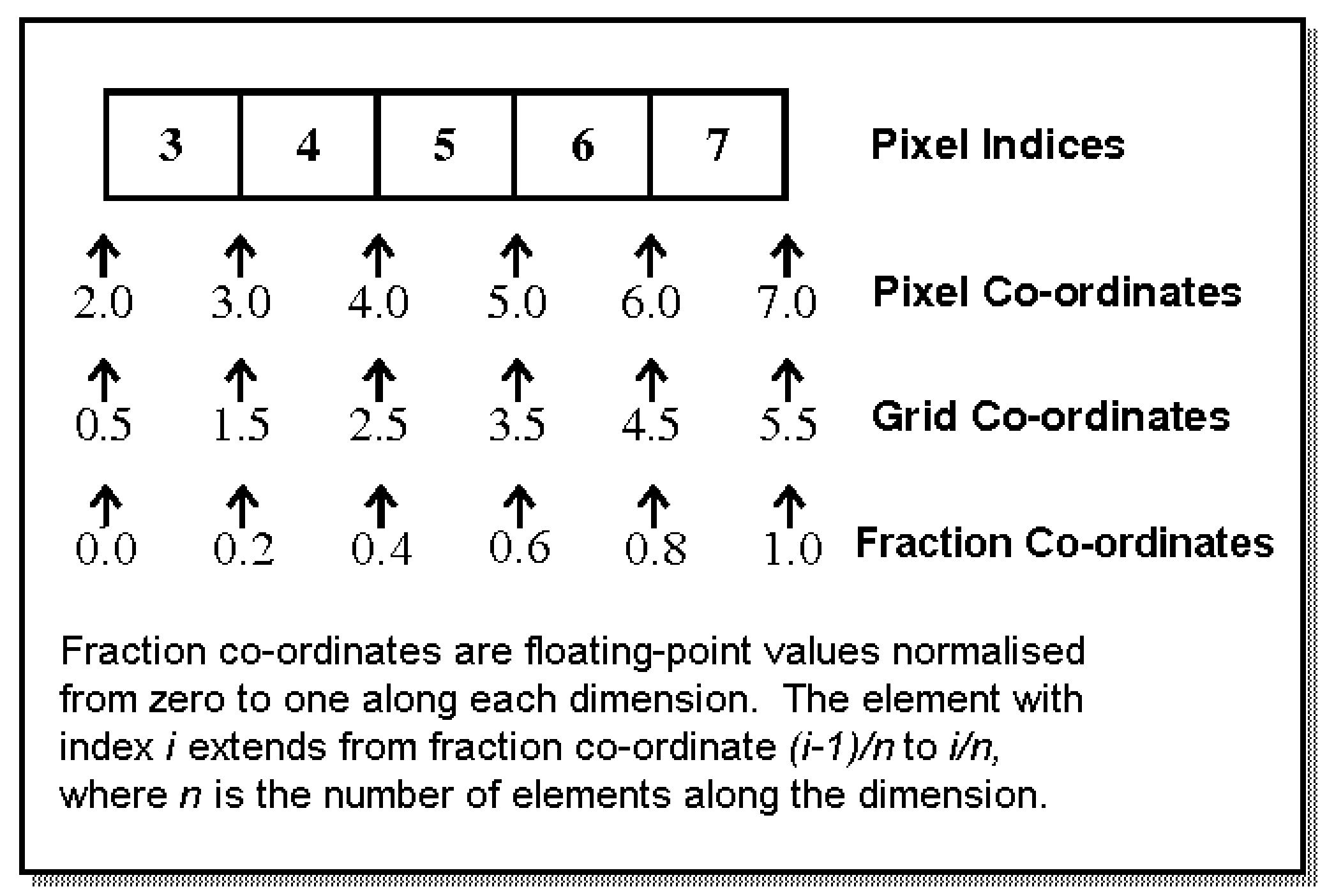
Fraction co-ordinates are floating-point values that are normalised pixel or grid co-ordinates such that each axis extends from zero to one. Thus in Figure 13 pixel co-ordinate 2.0 or grid co-ordinate 0.5 becomes 0.0 in fraction co-ordinates, and pixel co-ordinate 7.0 or grid co-ordinate 5.5 becomes 1.0 in fraction co-ordinates.
A co-ordinate Frame is a system of co-ordinate axes which can be used to specify a position within an NDF data array. Within an NDF such co-ordinate Frames also have associated descriptive information such as axis labels, axis units, a Frame title, etc. These are called the attributes of the Frame, and the most commonly used are listed briefly below (full descriptions of these attributes are included in Appendix D.
| Digits | : Number of digits of precision |
|---|---|
| Domain | : Physical domain described by the co-ordinate system |
| Epoch | : A date & time that defines the co-ordinate system |
| Format(axis) | : Format specification for axis values |
| Label(axis) | : Axis label |
| Naxes | : Number of Frame axes |
| Symbol(axis) | : Axis symbol |
| System | : Specific co-ordinate system used to describe the domain |
| Title | : Frame title |
| Unit(axis) | : Axis physical units |
The single most important attribute is the Frame Domain, which is an uppercase character string indicating the physical domain in which the co-ordinate system is defined. Frames with the same Domain can, in general, be aligned with each other.
Frames with the following Domain values are defined within every NDF, no matter how the NDF is created.
An AXIS structure is a one-dimensional array that maps pixel index along a given axis on to another related co-ordinate axis (e.g. wavelength) – the values on the other axes are assumed to be constant. Each dimension in the NDF should have an associated AXIS structure. Such structures can be created (for instance) using SETAXIS. If the NDF does not have defined AXIS structures, then a default AXIS Frame will be used in which the values along each axis correspond to pixel co-ordinates.
AXIS structures can only be used to represent independent axes. For instance, celestial co-ordinates cannot (in general) be described using AXIS structures because celestial longitude and latitude may both vary along any given row or column of an NDF.20 If an application is used that renders the AXIS structures in an NDF invalid, then the AXIS structures will not be copied to the output NDF. For instance, if ROTATE is used to rotate an NDF by an angle that is not a multiple of 90° , then the output NDF will not have any AXIS structures, and so the AXIS Frame will default to pixel co-ordinates.
The dimensionality of each of these Frames is equal to that of the NDF (e.g. a two-dimensional NDF will have two-dimensional PIXEL, FRACTION, GRID, and AXIS Frames). Axes within a Frame are identified by an integer index in the range 1 to the number of axes in the Frame. The above Frames are not stored permanently in the NDF, but are generated automatically by the NDF access library each time a reference is made to them.
In addition to the PIXEL, FRACTION, AXIS, and GRID Frames, an NDF may also contain any number of additional co-ordinates Frames. Descriptions of these extra Frames, together with recipes for converting positions between them, are stored permanently in the NDFs WCS component which may be examined using the NDFTRACE command. Application WCSADD allows new Frames to be added to the WCS component (positions in the new Frame must be related to the corresponding positions in an existing Frame by one of several different supported types of Mapping). WCSREMOVE allows Frames to be removed from the WCS component.
Two common additional Frame Domain options are SKY and SPECTRUM. SKY is reserved to refer to two-dimensional Frames that describe celestial longitude and latitude (known as ‘SkyFrames’). SPECTRUM is reserved to refer to one-dimensional Frames that describe position within a spectrum (known as ‘SpecFrames’). These sub-classes of Frame have additional attributes indicating the particular celestial or spectral co-ordinate system in use (e.g. equatorial, galactic, ecliptic, wavelength, frequency, radio velocity, optical velocity, etc.), and any required qualifying parameters (equinox, rest frequency, standard of rest, etc.). Instances of these Frames can be added to an NDF by importing suitable FITS headers using FITSDIN, FITSIN or the CONVERT package (see SUN/55). Alternatively, a SkyFrame can be created directly by specifying the pixel co-ordinates of stars with known celestial co-ordinates (see SETSKY and Gaia ).
Any co-ordinate Frames described in the WCS component, together with the standard GRID, FRACTION, PIXEL, and AXIS Frames, form a collection of inter-related Frames called a FrameSet. A FrameSet contains descriptions of each Frame, plus recipes (called Mappings) describing how to convert positions from one Frame to another.21
Frames within a FrameSet are distinguished by their attribute values, primarily their Domain value. In addition, each Frame has an integer Frame index. These indices are (in general) allocated sequentially in chronological order as Frames are added into the FrameSet. Applications that require the user to specify a Frame will usually allow the Frame to be specified either by Domain name, or by index. Frame indices can be examined using NDFTRACE (see below).
One Frame within the FrameSet of an NDF is nominated as the current co-ordinate Frame. When-ever an application reports positions within an NDF (for instance, when annotating plot axes), the positions reported will refer to the current co-ordinate Frame. Likewise, when-ever an application requests a position from the user (for instance, the position to be placed at the centred of a displayed image), it will expect the position to be given within the current co-ordinate Frame of the NDF,
The contents of the WCS component of an an NDF can be examined using NDFTRACE. By default, this just shows the number of co-ordinates Frames defined within the NDF (including the four standard ones), and the Title and Domain of the current co-ordinate Frame. More detail can be obtained using the keywords FULLWCS and FULLFRAME. The first causes the Title, index and Domain of all Frames to be displayed, together with the index of the current Frame. The second causes a more complete description of each Frame to be displayed, including axis labels, units, celestial co-ordinate system (for SkyFrames), etc.
The current co-ordinate Frame can also be examined using WCSFRAME. This is an important application because it also allows you to change the current co-ordinate Frame in the NDF. For instance:
will make the PIXEL Frame the current co-ordinate Frame in the NDF m31. After this, all references to positions within the NDF m31 will refer to pixel co-ordinates. You can also change the current co-ordinate system using WCSATTRIB:
The above changes the values of the ‘System’, ‘Unit’ and ‘SOR’ attributes of the current Frame in the NDF myspectrum so that it represents heliocentric frequency in units of GHz (this assumes that the current Frame in myspectrum is a SpecFrame since only a SpecFrame supports these particular attribute values).
New co-ordinates Frames can be created and added into an NDF using WCSADD. When you create a new Frame you should give it a meaningful Domain name which indicates the sort of co-ordinates that it represents. You are free to choose any name you like (white space is removed, and lower case characters are converted to upper case before using the supplied Domain string), but you should usually avoid the following reserved Domain names:
When two Frames are joined together to form a compound Frame describing a co-ordinate space of higher dimensionality, the default Domain name for the compound Frame is formed from the individual Domain names, separated by a hyphen. For instance, the WCS FrameSet associated with a spectral cube will often contain a (compound) Frame with the Domain name “SKY-SPECTRUM”. Thus you should also avoid Domain names that contain a hyphen, particularly if they also contain any of the reserved Domain names listed above.
Several applications (WCSFRAME, CURSOR, LISTMAKE, etc.) have parameters that are used to select a co-ordinate Frame. These parameters are usually called FRAME. When selecting a Frame from an existing FrameSet (e.g. read from the WCS component of an NDF), the Frame may be specified in one of the following ways:
An SCS specification is made up of two parts; a co-ordinate system name, followed by an optional epoch giving the reference equinox. Any of the three system names EQUATORIAL, ECLIPTIC and GALACTIC can be used. Case is insignificant, and abbreviations may be given.
Ecliptic and equatorial co-ordinates are referred to the mean equinox of a given epoch. This epoch is specified by appending it to the end of the name of the sky co-ordinate system, in parentheses; for instance EQUATORIAL(1983.5) (only the four most significant decimal places are used). The epoch may be preceded by a single character, B or J, indicating if the epoch is a Besselian epoch (B) or a Julian epoch (J). If this character is missing (as in the above example), then the epoch is assumed to be Besselian if it less than 1984.0, and Julian otherwise. If no equinox is specified in this way, then a default of B1950.0 is used.
If a Julian epoch is used to specify the reference equinox for an equatorial co-ordinate system, then the equatorial co-ordinates are assumed to be in the IAU 1976, FK5, Fricke system. If the equinox is specified using a Besselian epoch, then the co-ordinates are assumed to be in the FK4, Bessel-Newcomb system.
When a Frame is specified using an SCS specification, it will usually also be necessary to specify the epoch at which the positions were determined. This will be done using the separate Parameter EPOCH. This epoch is required because some celestial co-ordinate systems are non-inertial and rotate slowly with respect to other celestial co-ordinate systems, introducing fictitious proper motions. Knowing the date at which the positions were determined allows the effect of this fictitious proper motion to be eliminated when converting between different systems.
When specifying a new Frame (rather than selecting an existing Frame from a FrameSet), you can either give a Domain name, or an SCS specification, but you cannot give a Frame index. Any string may be used as a Domain name, and you will usually be required to specify the number of axes in the Frame. The exception to this is if you specify one of the Domain names SKY, GRAPHICS, NDC, CURPIC or BASEPIC, in which case a two-dimensional Frame is always created.
The nature of the current Frame can also be changed using WCSATTRIB, which allows new values to be assigned to specified Frame attributes. For instance, assigning a new value to the System attribute will change the co-ordinate system used to describe positions within the domain covered by the Frame. The main attributes relevant to Frames are described in Appendix D.
Kappa applications that create an output NDF on the basis of a given input NDF usually copy the contents of the WCS component from the input to the output, modifying it as appropriate to take account of any linear mapping of pixel co-ordinates introducing by the application. The following are exceptions to this rule:
The output NDFs produced by such applications will contain no WCS component (but they will still have the four standard Frames—GRID, FRACTION, PIXEL and AXIS—albeit the AXIS Frame will probably just describe pixel co-ordinates since these applications will not usually copy the AXIS structures either).
The application WCSCOPY can be used to copy the WCS component from one NDF to another, optionally introducing a linear transformation of pixel co-ordinates in the process. This can be used to add WCS information back into an NDF that has been stripped of WCS information by one of the above applications.
When a Kappa application requires WCS information, it looks first in the WCS component of the NDF. If no WCS component is defined within the NDF, then it will attempt to obtain WCS information from two other locations, in the following order:
Note, Kappa applications always write WCS information in the form of a standard WCS component. You should remember that astrometry information stored within an IRAS90 or FITS extension will not be corrected to take account of geometric manipulation produced by applications such as ROTATE, COMPAVE, etc. Use of such applications will render IRAS90 and FITS astrometry information incorrect. For this reason, applications always warn the user if astrometry information is being read from an IRAS90 or FITS extension. These extensions can be deleted if necessary, using the ERASE command. For instance:
will erase the IRAS90 and FITS extensions from the NDF m31.
As mentioned in the previous section, the SETSKY application stores astrometry information within an NDF in the form of either a WCS component or an IRAS90 astrometry structure.
To use SETSKY, you need to know the celestial co-ordinates at a set of points within the image. You may be able to find these by comparing your image with other images, such as those available from the Digitised Sky Survey, which already have astrometry information associated with them. You create a text file holding the pixel and celestial co-ordinates at a single position on each line. For instance, if you have five known RA/DEC (B1950) positions in your image, the file may look like:
The first column gives the RA values (hours, minutes and seconds), the second gives the DEC values (degrees, arcminutes and arcseconds), the third gives the pixel X co-ordinates, and the fourth gives the pixel Y co-ordinates.
If this file is called pos.dat, then the following command can be used to create a WCS component:
Note the up-arrow character ("^") before the file name (pos.dat). This tells SETSKY that the string is a file name. A gnomonic (or tangent plane) projection was requested using the PROJTYPE parameter. If no projection type is specified then SETSKY will try four different projections (gnomonic, Aitoff, Lambert equivalent cylindrical, and orthographic) in turn, and choose the one that gives the smallest RMS position error.
An alternative way to add a celestial co-ordinate Frame to an NDF is to use the facilities of GAIA (see SUN/214). This provides much more sophisticated facilities.
For many years, the calibration of spectral axes has been recorded in the form of AXIS structures within the NDF. As mentioned above, each pixel axis in an NDF has an associated AXIS structure, which is a one-dimensional array containing an element for each pixel on the associated axis. The value of each element gives the ‘axis’ value for the pixel.
Spectral axis calibration can now also be recorded in the form of a ‘SpecFrame’ within the WCS component. A SpecFrame is a Frame that can describe spectral axes in many different forms (wavelength, frequency, various forms of velocity, etc.), with many different units, and measured in various rest frames. A SpecFrame ‘knows’ how to convert between all these different forms. Let’s say you have two spectra—in one the current co-ordinate Frame is a SpecFrame representing frequency in GHz as measured in the rest frame of the telescope (i.e. ‘topocentric frequency’), and in the other the current co-ordinate Frame is a SpecFrame representing radio velocity in km/s measured in the kinematic Local Standard of Rest. You want to overlay plots of these two spectra for comparison purposes, so you display the first using LINPLOT. This produces a plot in which the x axis is frequency measured in GHz. You then display the second spectrum, again using LINPLOT but this time specifying clear=no on the command line in order to prevent the previous plot from being erased. The SpecFrame representing radio velocity in the second spectrum automatically adjusts itself to represent the same system as the currently displayed plot (topocentric frequency in this example), so the plots can be compared directly. The conversion includes the effects of the Doppler shift caused by the differing standards of rest used by the two spectra.
So the question arises; “How can I add a SpecFrame to my existing NDFs that only have
an AXIS structure?”. This is simple to do using the WCSADD command. Let’s assume
you have a one-dimensional NDF called fred containing an AXIS structure holding the
frequency at the centre of each pixel in units of GHz. The following command will add an
appropriate SpecFrame to the WCS component of the NDF (and will also make it the current
Frame):
The FRMTYPE parameter indicates that a SpecFrame should be created. The ATTRS parameter gives the attribute values to be assigned to the SpecFrame (note the quotes to protect the string from interpretation by the UNIX shell). The DOMAIN parameter is given the default domain for a SpecFrame (and should usually not be changed). The MAPTYPE and FRAME parameters indicate that this new SpecFrame should be connected to the existing AXIS Frame using a UnitMap—i.e. the frequency values held within the AXIS structure are identical to the frequency values described by the SpecFrame.
The above setting for the ATTRS parameter gives the bare minimum of information—there are several other items of information that could have been given. For instance, the above command does not indicate the standard of rest to which the frequency values refer. Neither does it indicate the source position, date of observation, or the observers geographical position (all of which may be needed to enable conversion between different standards of rest). In general you should specify as much information as you can. To do this, you can either include the extra information in the ATTRS parameter value above, or you can add the information later using WCSATTRIB. For example:
These commands set new values for named attributes within the current Frame of NDF fred. These
attributes are described in Appendix D. The inclusion of "remap=no" is important: it tells the
command to change the Frame attribute without changing the Mappings between Frames
accordingly. If the default value of "remap=yes" were used, the Mappings that connect the
SpecFrame to the other Frames within the WCS FrameSet would be modified in order to ensure that
the position of each pixel is unchanged. The default mode ("remap=yes") should be used if you
already have a fully and correctly specified SpecFrame within the WCS component which you want to
change to describe a different system. For instance, if you have a SpecFrame describing frequency at
each pixel, and you want to change it so that it describes the corresponding wavelength at each pixel,
then doing:
will modify the Mapping between the pixel Frame and the SpecFrame using the relationship “wavelength = speed of light/frequency”.
However, if you have a partially or incorrectly specified SpecFrame you should usually use
"remap=no". For instance, of the above SpecFrame, which gives the frequency at each pixel, was
discovered to be incorrect in that the AXIS values were actually wavelength values and not frequency
at all, then you would want to correct the WCS component by changing the System attribute of the
SpecFrame from "freq" to "wave". In this situation you want to leave the Mapping from the pixel
Frame to the spectral Frame unchanged since the Mapping already gives the correct wavelength
value (previously, but erroneously, thought to be a frequency value). So here you would
do:
Let’s say you have a spectral cube in which the WCS axes are wavelength, RA and Dec. In this case,
the current co-ordinate Frame will actually be a ‘compound’ Frame containing two ‘component’
Frames; a one-dimensional spectral Frame and a two-dimensional sky Frame. If we consider an
attribute such as System (which all classes of Frame have), we now seem to have three different
Systems to consider; the System value for the component spectral Frame, the System value for the
component sky Frame and the System value for the compound Frame as a whole. So if we want to set
the spectral system to "optical velocity", and celestial system to "Galactic" what do
we do? The answer is to include the index of an axis within the attribute name. If WCS
axis 1 is the spectral axis, 2 is the RA axis and 3 is the Dec. axis, then we would do the
following:
In fact, we could have used "System(3)" in place of "System(2)" since Axes 2 and 3 are both
contained within the same sky Frame and so setting the System attribute for either one will have the
same effect. We could now examine the attributes as follows:
These commands will display vopt and Galactic, as expected. Note, the following command:
will display Compound since it is displaying the System value of the compound Frame as a whole
(because no axis index was included).
To continue this example, the SpecFrame class (which represents spectral axes) has an attribute called StdOfRest (standard of rest). This attribute is specific to the SpecFrame class and is not recognised by other classes of Frames. If we do:
we will get an error saying the attribute name is unknown. This is because compound Frames do not have a StdOfRest attribute. If we want to set the standard of rest, we must indicate the index of the spectral axis as follows:
Likewise, if we wanted to set the Equinox attribute of the sky Frame, we could say:
20For this and other reasons, new applications will avoid using AXIS structures, and make use of the more versatile WCS component instead.
21A Mapping need not necessarily be defined in both directions. For instance, a Mapping that goes from a three-dimensional Frame to a two-dimensional Frame (maybe by simply throwing away one of the axis values) may not be defined in the other direction. KAPPA applications will report an error if a Mapping is not defined in the required direction. Another common example of a uni-directional Mapping is that between the GRID and AXIS Frames in cases where the AXIS structures are non-monotonic.